* OPTION RTCP
Option RTCP ( Rotation Tool Center Point ) is applicable on machine tools equipped with head Bi-rotary printing-press or kinematics to plates. This function makes it possible to program in 5 axes while referring directly to the center of the tool instead of the centre of rotation of the axes (i.e. at the Pivot point).
It allows also the tool length compensation in space. Moreover thanks to function RTCP it is possible in mode IMD (Manual entry of data) or by crank, to carry out machining in 5 axes of surfaces programmed in 3 axes (provided that this machining is carried out with a cutter swell).
* ANALYZE PROGRAMMING OF THE AXES
In the case of machine 5 axes, the rotational movement of an axis causes the displacement of the centre of rotation of the head (or the plate) of a value proportional to the swing angle and the distance from the center of the tool in the centre of rotation of the axis.
This displacement is represented schematically in the following figure:
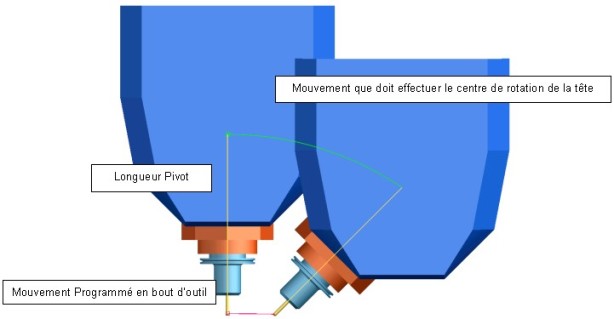
In the case of the rotation of only one axis, the displacement of the center of the tool occurs in a plan, with the rotation of two axes, this displacement occurs in space.
* PROGRAMMING WITHOUT RTCP
To program in 5 axes the machining of surfaces, it is necessary to know the distance between the center of the tool and the center of the rotary head: this distance is called Length pivot. According to the value of this length and value of rotation of the axes, one will have to calculate linear value XYZ of compensation in order to maintain the center of the tool in the desired position.
The program thus obtained must be used on the machine with a length of pivot exactly equal to that which was defined in the program; each variation length implies a reprocessing of the program.
Function RTCP deals with maintaining the center of the tool in the programmed position. To maintain this position, each movement of the rotary axes is compensated by a linear displacement of axes XYZ.
* Without RTCP
The instruction “ N10 A90 F800″ causes a movement of axis A without movements on the axes XYZ which would make it possible the tool to remain in contact with the part.
* With RTCP
If option RTCP is activated, the same order “ N10 A90 F800″ causes the swing of 90° axis A with displacements of axes XYZ to maintain the end of tool to the same position.
In this way it is possible to program the course of the tool directly, without being concerned with length pivot: this value will be introduced directly by the operator via his CN before carrying out the program. One could almost thanks to Mode RCTP Calculer a course 5 axes without taking into account the kinematics of the machine.
* CORRECTION THE LENGTH TOOL
In the case of definite programs in a traditional way, option RTCP makes it possible to use tools different length that that which was considered during the creation of the program. Without this function the program must be obligatorily recomputed or Re-postprocesse with the exact values the lengths tools measured on the machine. The even negligible change of these values implies the creation of a new file.
* SPEED In advance
In standard programming, the speed of the center of the tool is equal at the programmed speed the speed resulting in the center of the head is proportional to the variation of the rotary axes and the value of pivot, but it also depends on the movement of the linear axes.
* EXAMPLE
N10 A90 C180 F1500
The speed of the center-tool is null, whereas the point pivot moves at a speed proportional to the length pivot and the angular variations of A and C.
Function RTCP thus allows also, to ensure better a management of the advances. The speed of the axes moving of the machine will be recomputed compared to displacement of the point pivot, so D ‘ to ensure a speed in advance conforms at the speed required in end of tool.
Synchronization between the axes not being always perfect, It often arrives which the linear axes is faster than the rotary axes. The tool is thus able at its final position before to have reached its angular positions. On a machine equipped with function RTCP the control of the synchronization of the axes being carried out in real time it is not necessary to resort to the level of programming FAO to palliative easy ways to this type of defect such as for example:
The limitation of the movements on the axes between two instructions CN ( maximum distance between two points, or angular variation maximum ).
Or to use programming in reverse of time.
* Note: programming in reverse of time
In this programming method programmed speed is not any more one speed to be reached but a time to carry out the movement. This type of programming with for effect to make sure that the rotary axes have sufficient time to carry out their rotation. There are two disadvantages with my direction with this programming:
- A) It requires to give for each new instruction a time, the operator cannot thus intervene more to change in the ISO program the values in advance.
- B) This function “attaches” the advances of the machine: not being able to reach speed requested one slowed down the machine. One will thus tend to machine at a speed always lower at the speed atteignable if it were managed in mode RTCP
*RTCP FOR PROGRAMS 3 AXES
The programs 3 axes obtained by programming FAO, can be carried out, via function RTCP, in 5 simultaneous axes. This programming is possible if spherical tools are used. The movement of the rotary axes, is then controlled by the operator in IMD or cranks. The slope of the tool allows the use of cutter length lower than those which are used for machinings 3 axes.
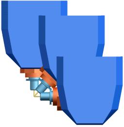
Machining a) 3 axes b) 3 axes + RTCP
In the a) part of the figure is represented a part which, to be machined in 3 axes, requires the use of a tool a considerable length, in order to avoid collisions between the pin and the part. The b) part of the figure shows how, thanks to the slope of the head one can carried out the machining of the same surface with a tool lower length. The slope will have to be modified manually by the operator during the execution of the program 3 axes.
>>>> Source collectibles……..
